Crumpling cabinet feet/wheel mounts: jerry-riggin’ a solution
Back in September, I mentioned modding some vintage metal filing cabinets by replacing #3/8-16 screw-on foot pads with M10-bolt stainless steel wheels. That project entailed re-doing the threads in the holes on the footpad mounts by tapping the screw holes. It seemed to work perfectly and, at the time, I was quite pleased with myself.
These filing cabinets are being employed as general-purpose storage. They’re filled with needful things of modest weight, not (for example) lead ingots or gold bars. Nothing heavy has been stacked on top of them and nobody has been using them for, say, box jumping. Recently, when moving them around, they didn’t seem to be rolling as expected.
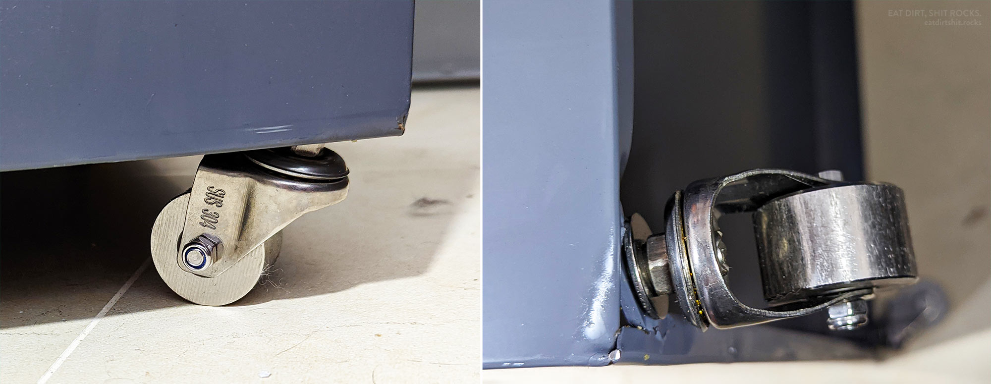
To my surprise, upon closer inspection, it turned out that some of the wheels on each of the cabinets was angled, to varying degrees, inwards. Poking around a bit more, I could see that the mounting points, the metal tabs spanning the corners of the folded-over bottom edges of the cabinets’ sheet metal walls, were no longer parallel to the floor. At the points where they were welded onto the cabinets’ thin sheet metal, the sheet metal was deformed, buckling upwards in an arc towards the cabinet bottoms. The image above, made by combining two photos of one of the worst-affected wheels, is worth a thousand poorly-chosen words.
In retrospect, had I been a wee bit wiser, I might have anticipated this sort of issue. The metal pads installed by default were tightened all the way and their upper faces nestled against the tabs whereas the wheels that I installed elevated the cabinets several centimeters above the floor. And the mounting tabs were likely very slightly non-perpendicular when I swapped the feet out for the wheels. I’m not a mechanical engineer, so I lack the expertise that would allow me to come up with the correct technical gloss here, but my hunch is that (in ignorant layman’s terms) something like a cantilever effect was at work.
Giving it a hard think, groping for a simple, durable, and non-destructive solution, I settled on making a wooden mega-shim to better-distribute the load on the wheel mounts from the weight of the cabinets.

and two of the plank pieces and a heap of the plywood squares before I screwed them together (RIGHT).
A bit of measuring with digital calipers gave me a gap between the tabs and the inside bottom of the cabinet of approximately 35mm. The original drilling and tapping of the mounts had deformed the tab material upwards around the rims of the holes, so the gap is a little less than 35mm in those areas. I knocked together 35mm-thick shims by screwing squares of 5mm-thick plywood onto the wider face of pieces of 3cm-by-10cm pine board, at the ends so they’d be under the mounting holes. Each cabinet would need two of them, one for the front pair of wheels and one for the rear wheels.
The inside bottom of one of the cabinets is nearly exactly 375mm wide, but the shims had to be a bit shorter because of the upturned lips of all of the pieces of sheet metal that comprise a cabinet’s sides. Shaving a centimeter off the length (i.e. 365mm) made them just short enough that I could tap them into being parallel with a dead-blow hammer after tilting them slightly to get them past that lip.
My workflow went like this: First, after removing the wheels, un-warp a pair of wheel mounts using the claw end of a hammer with an “indexing” claw as a prybar. Second, insert the shim with the plywood squares facing outwards (contacting the wheel mount holes) and tap it parallel and then all the way up and under the mounts. Third, (by hand, using a hex-shank 8mm drill in a ratcheting bit holder) drill undersized holes through the M10 threaded holes in the mounting tabs and into the wood, to accommodate the upward-extending bolt ends of the wheels. Finally, after vacuuming out the wood shavings, re-insert the wheels. Once the bolt tip emerged into the 8mm-diameter hole in the plywood and the pine board, the going got tougher and pliers were needed.
The second photo in this post shows one set of reinforced wheels on one of the cabinets.
Some of the tools that I used are shown in this next image:
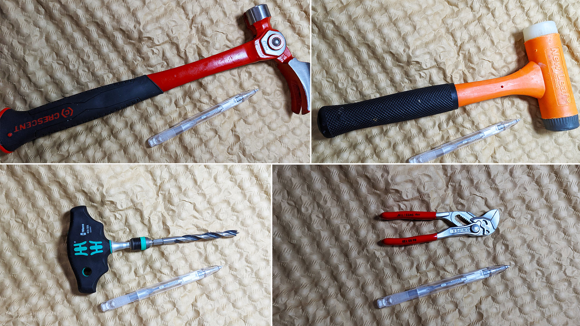
For scale, I included a mechanical pencil in each of the tool snapshots.
A few days have passed and the fix seems to have been successful, at least for now. Famous last words.